

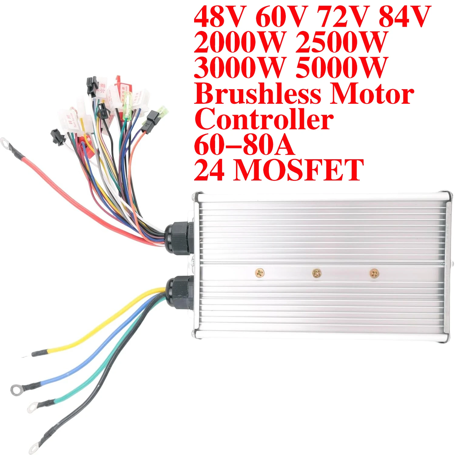
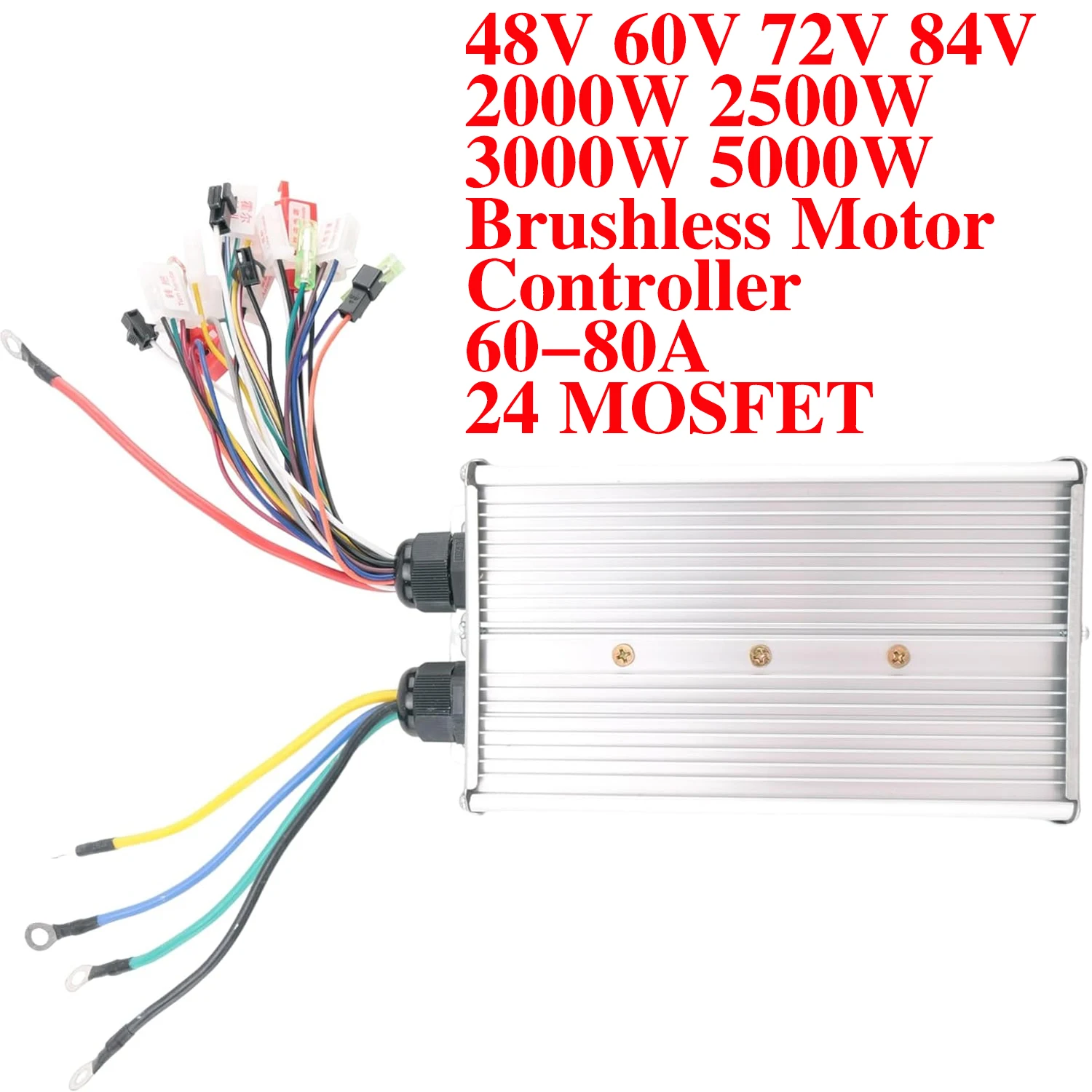
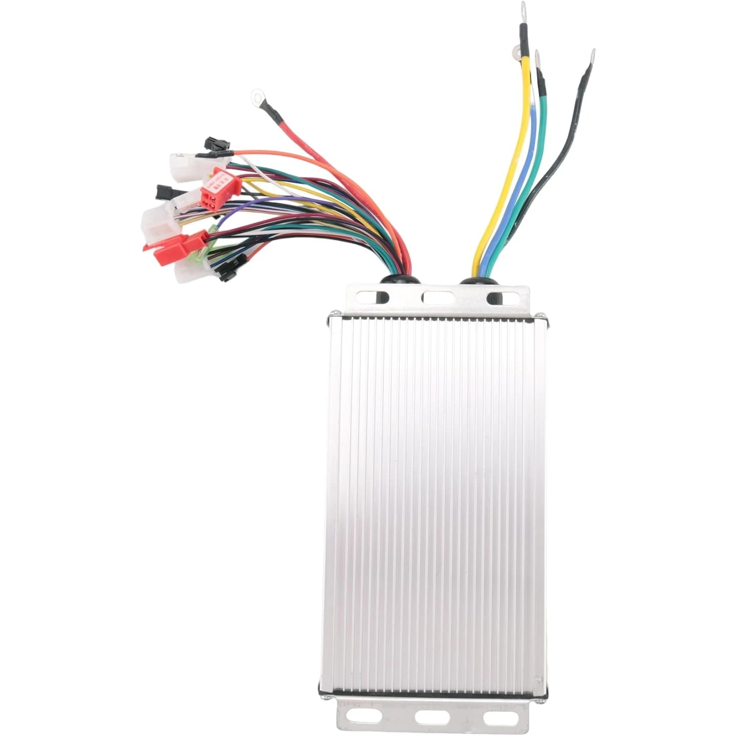
48V 60V 72V 84V 2000W 2500W 3000W 5000W Brushless Motor Controller 60-80A 24 MOSFET Dual Mode Controller for E-Bike Motorcycle
$170.93
- High-concerned chemical: None
- Type: Controller
- Origin: Mainland China
- 48V: 60V
- 72V: 84V
- 2000W: 2500W
- 3000W: 5000W
- Brushless Motor Controller: Motor Controller
- Lithium battery controller: controller
- 24 MOSFET: 24MOSFET
2. Please allow slight manual measurement deviation for the data.
1. The actual color of the item may be slightly different from the picture shown on the website, which is caused by many factors such as monitor brightness and light brightness.
Note:
1 x controller
Package includes:
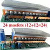
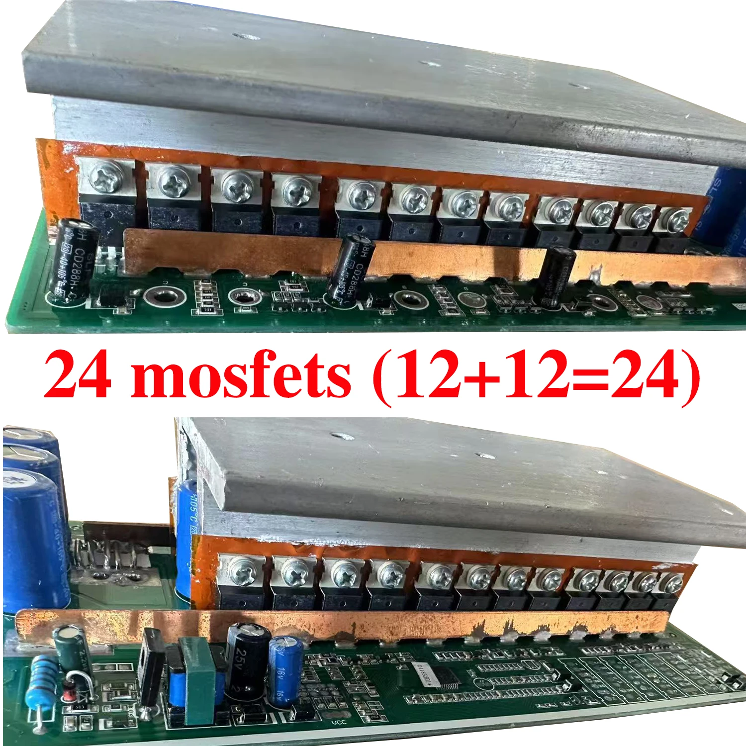
2000-2500-3000-5000w : * is 24 mosfet
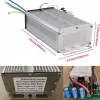
*Weight: about 1.65kg
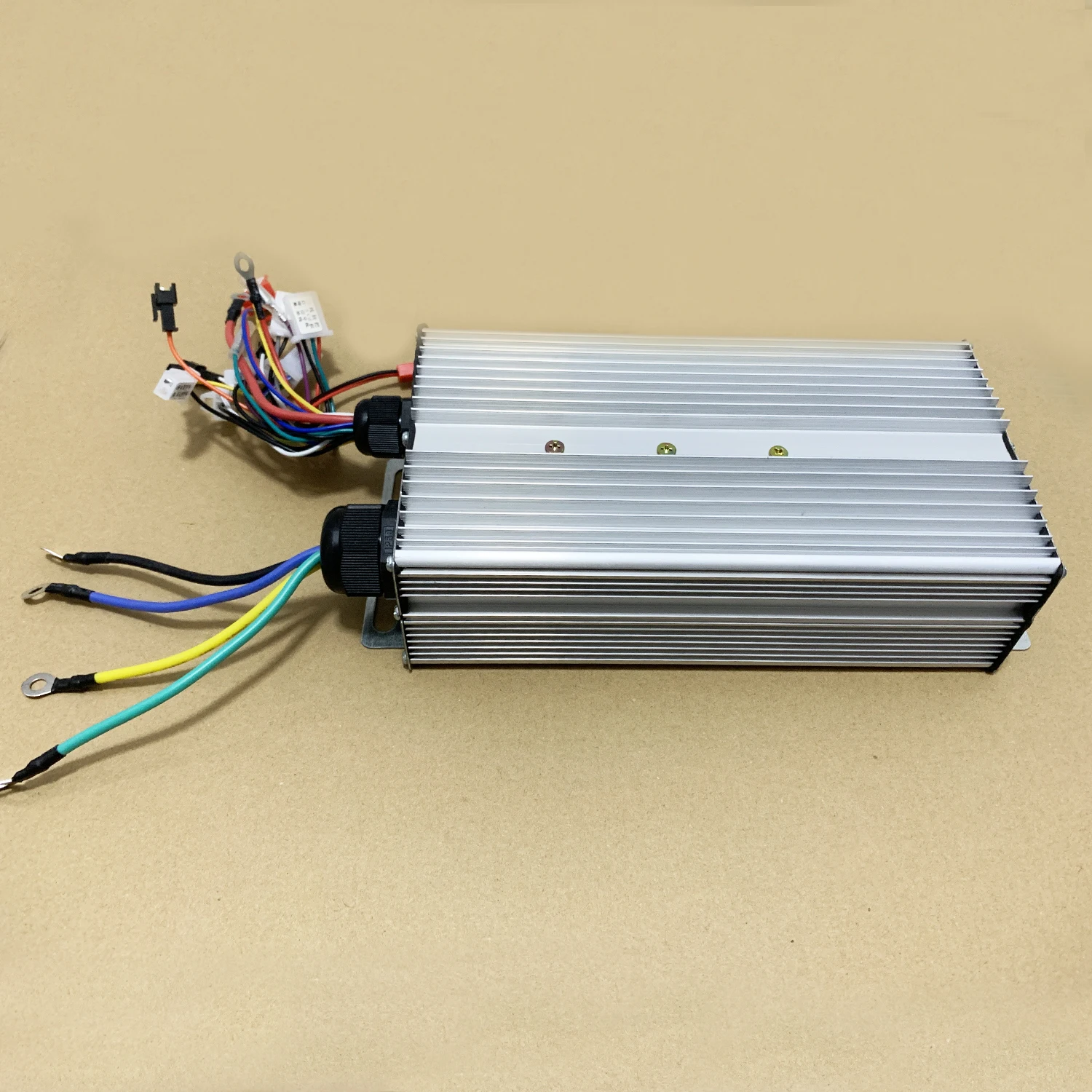
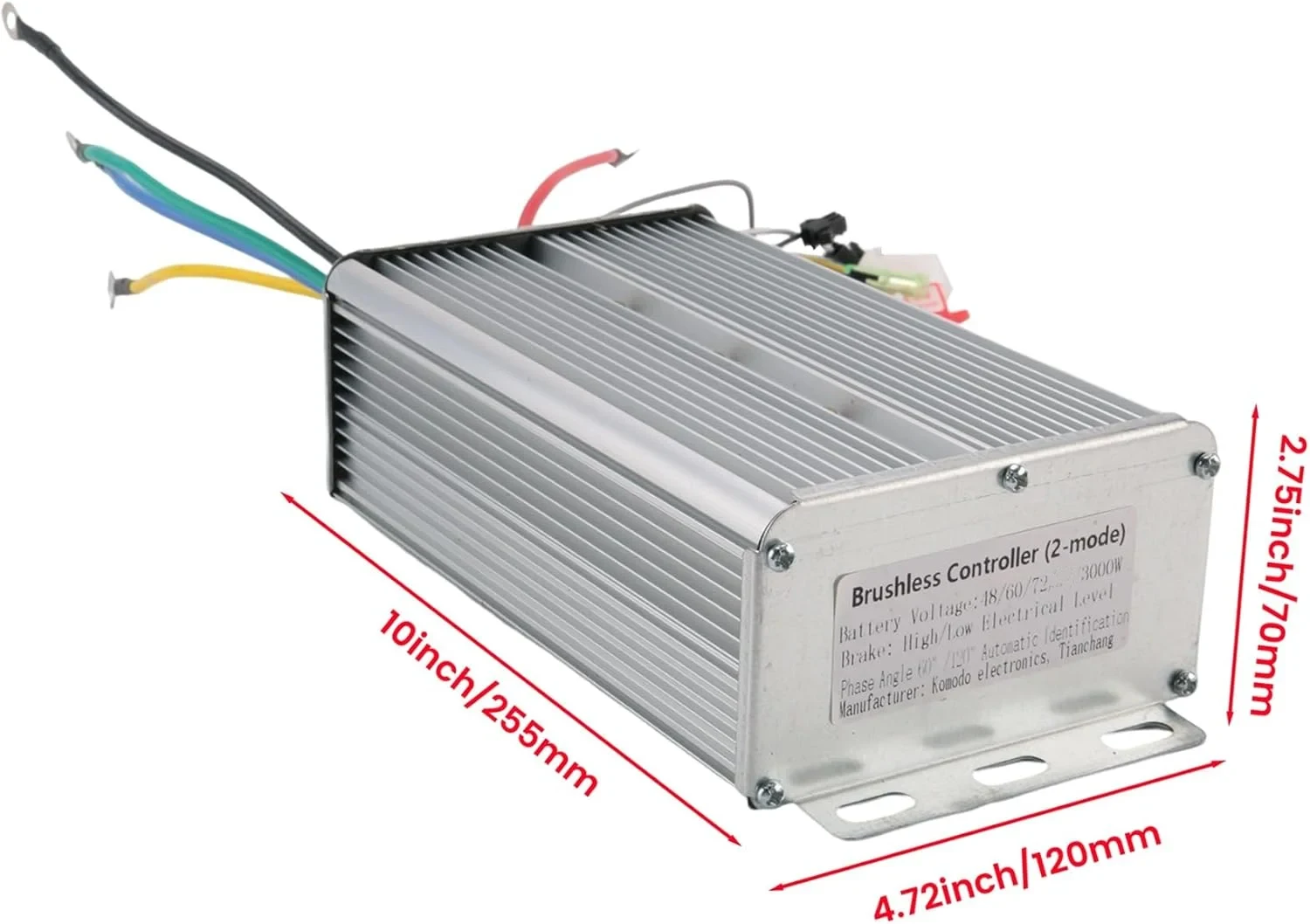
*Size: 260x120x70mm
*Color: silver,
*Material: plastic + metal
Specifications:
*Product function: switch three-speed, intelligent cruise, anti-theft, reverse, one-button start
*Tricycle, four-wheel vehicle, bicycle, scooter lithium battery modification controller set
*Applicable to Hall motor and Hall-free motor
2000-2500-3000-5000w : *Applicable to 1000W 1500W 2000W 3000W 5000W 60-80A
*Applicable to 60A-80A
*Applicable to 48V 52V 60V 72V 84
*Waterproof level: splashproof
*Turning handle voltage: 1.1±4.2V
*Brake battery: high/low battery
*Made of high-quality materials, practical
*Brand new and high quality
Description:
Must match communication protocol 2 to use the instrument
Follow the tutorial at the bottom of the detailsThe driver is communication protocol 2
[Exquisite workmanship]: Our products are professionally manufactured, with stable performance, increased shell thickness, and better heat dissipation. High reliability.
[Outstanding upgrade accessories]: motor has thicker copper bars, higher inductance accuracy, smoother starting, and more comfortable riding.
[Excellent performance]: The motor has strong climbing ability and low motor running noise, eliminating tire noise.
[Scope of application]: it is a wide voltage controller, 48V 60V 72V 84 can be universal, the maximum current limit is 80A(It does not mean that the output current is 80A, it only means that the controller can withstand a maximum current output of 80A. The current output size is also related to the battery and motor.), and it can be applied to brushless motors.
The uphill torques of the controller is increased, the power is strengthened, the speed can be faster, the smoothness of motor is better, and the life of the controller is longer.
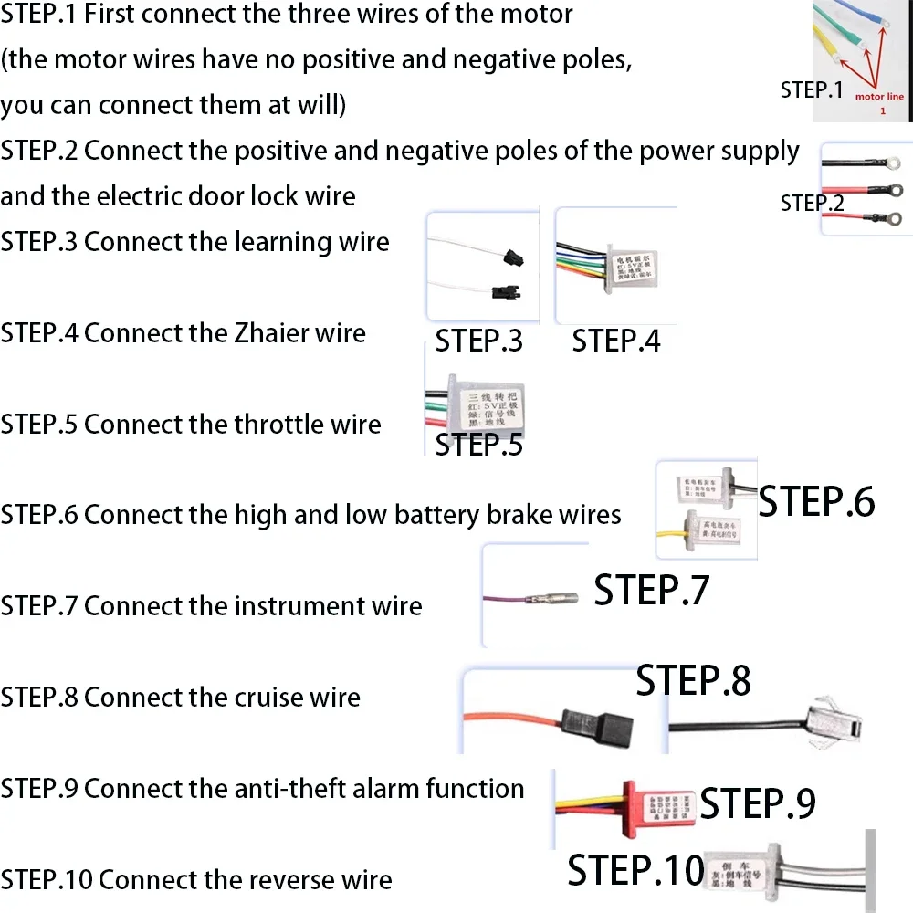
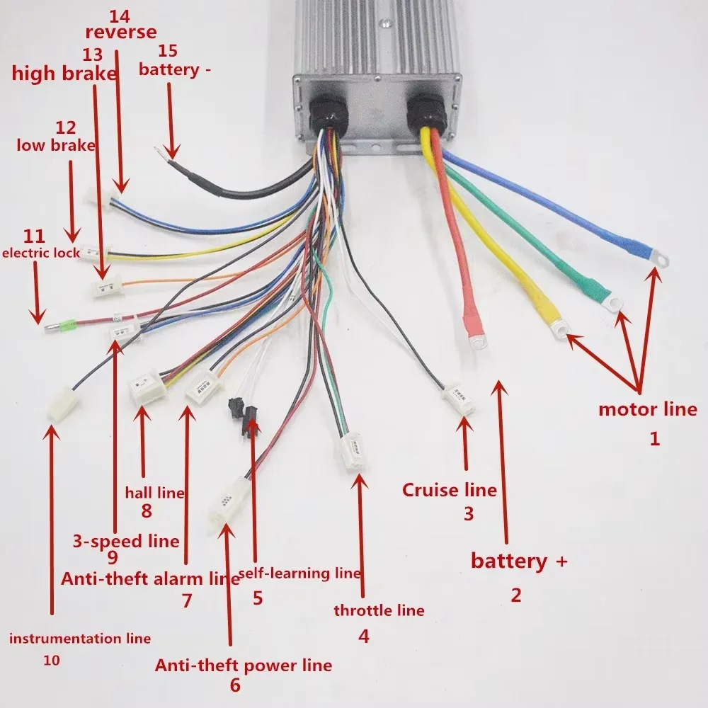
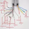
STEP.1 Connect the three motor wires first (the motor wires have no positive or negative poles, so you can connect them at will)
Connect
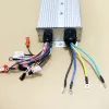
the three thick yellow, green and blue motor wires with the three motor
wires of the electric vehicle, shake the rear wheel with your hand to
feel if there is any resistance, if there is no resistance, proceed to
the second step, if there is resistance, check if the three motor wires
are not connected properly. (How to detect whether the motor is good or
bad: touch the motor wires of the electric vehicle two by two, if there
is resistance, it means the motor is good, if there is no resistance, it
means the motor has a problem).STEP.2 Connect the positive and negative poles of the power supply and the electric door lock wire
The
power wire of the controller, the thick red is the positive pole, the
thick black is the negative pole, and the thin red wire is the electric
door lock wire, which can be matched with the positive and negative
poles of the power supply and the electric door lock wire of your
electric vehicle! (Note that the positive and negative poles of the
power supply must not be connected in reverse, otherwise the controller
will be burned. If the electric vehicle does not have an electric door
lock wire, the electric door lock wire on the controller and the
positive pole of the power supply can be short-circuited together)STEP.3 Connect the learning wire
There
is a pair of white learning wires on the controller. Plug the learning
wires together, then plug in the power key, turn on the power, and see
if the motor rotates automatically. Forward rotation, just unplug the
learning wire. Reverse rotation, unplug the learning wire, and re-plug
it to become forward rotation, then unplug the learning wire to complete
the learning (after this step is completed, the motor automatically
rotates to prove that the controller is good, and if it does not rotate,
it proves that the controller has problems)STEP.4 Connect the Hall wire
Plug in the Hall wire. The Hall wire is 5 wires with one head. Note: The Hall has positive and negative poles
STEP.5 Connect the throttle wire
Find
the throttle wire for control, red, green and black, red is the
positive pole of the throttle, black is the negative pole of the
throttle, green is the signal wire of the throttle, then find the
throttle wire on the electric vehicle, note that the throttle wire of
the electric vehicle must come out from the throttle. If necessary, you
can disassemble the throttle to identify which one is the throttle
connector in the electric vehicle, connect the throttle connector, turn
the throttle, and see if the motor rotates. If there is no response when
turning the throttle at this time: 1. The positive and negative poles
of the throttle are not connected correctly;2. The throttle is
broken, just change a throttle. (Friends with a multimeter can use the
multimeter to test the throttle signal wire to see if there is a voltage
output. Set the multimeter to the voltage output state, connect the red
needle to the green signal wire of the throttle, and connect the black
needle to the black ground wire of the throttle to see if there is a
0-5V voltage. If there is no voltage, it proves that the throttle is
broken. Be sure to connect the controller and the throttle and turn on
the power to test, otherwise it will not work).STEP.6 Connect high and low battery brake wires
1.
There is a single yellow high battery brake wire on the controller, and
a white and black low battery brake wire. The high battery brake and
the low battery brake are distinguished by the brake voltage. If the
brake voltage is higher than 5V, use the high battery brake, and if the
brake voltage is lower than 5V, use the low battery brake. The effect of
high battery and low battery brake is to cut off the power of the
brake. First, identify how many wires come out of your brake handle, one
for the high battery brake and two for the low battery brake. (If your
car is a turn brake, you need to pull out the white and black of the low
battery brake and put it together with the turn handle wire to achieve
the effect of brake power off). 2. Because the EABS electronic brake is
built into the controller program, the electronic brake effect will be
generated as long as the brake is powered off. The electronic brake is
when the brake is powered off. The motor generates a reverse force to
brake. Sometimes there will be a "click" sound, which has no effect on
the motor. Please feel free to use it.STEP.7 Connect the instrument line
The
instrument line is a single thin green line, suitable for pointer
instruments. If it is a liquid instrument, please choose carefully,
there is a mismatch.STEP.8 Connect the cruise line
Cruise
is divided into automatic cruise (just plug the cruise line in) and
button cruise (just connect the two lines from the button to the patrol
line).STEP.9 Connect the anti-theft alarm function
The
anti-theft function line consists of two groups of lines: the anti-theft
power supply and the anti-theft signal. Among them, the red and black
lines of the anti-theft power supply represent the positive and negative
poles of the battery respectively, while the red line of the anti-theft
signal is the electric door lock line, the yellow line is the wheel
signal line, and the blue line is the anti-theft signal line. Be careful
not to connect the wrong lines!STEP.10 Connect the reverse line
The
reverse function is a closed circuit, connect according to your needs
(special reminder that the 350W controller does not have a reverse
function, if you need a reverse function, please make a note).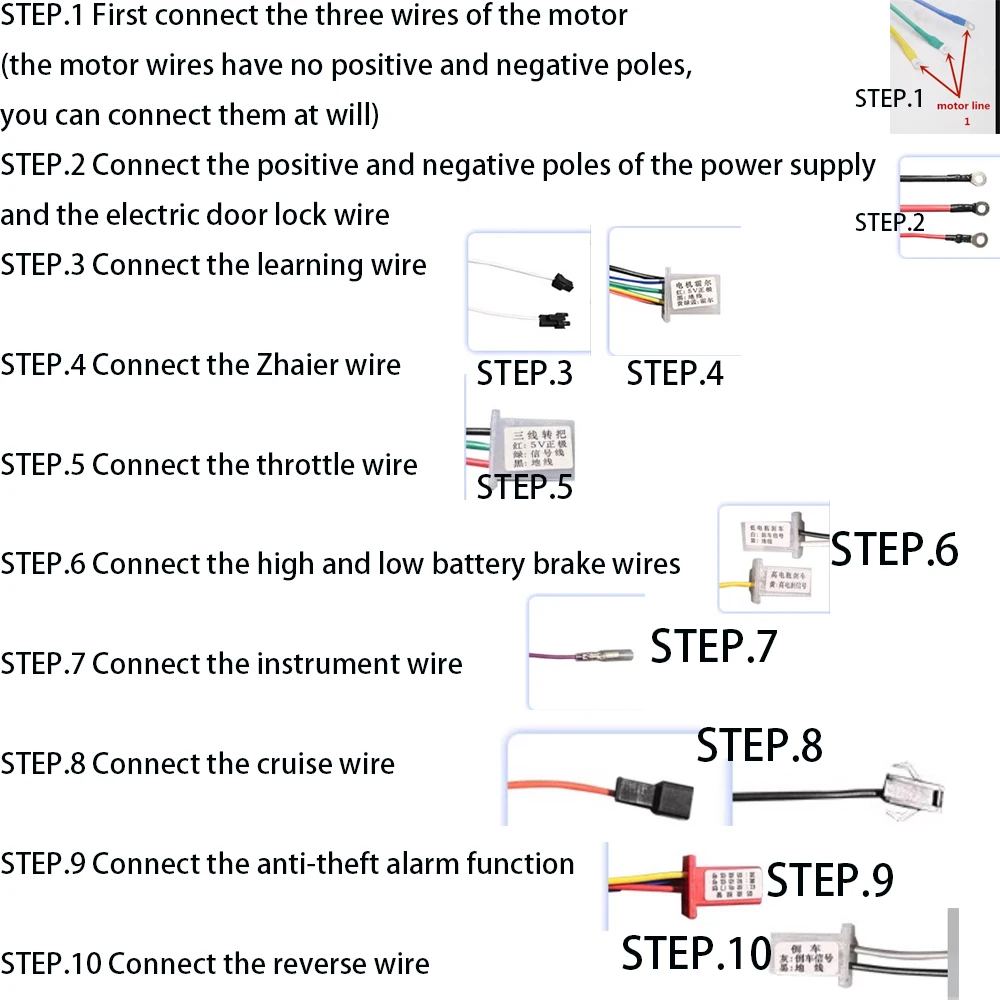

No ratings yet
Reviews
There are no reviews yet.